Venkon
Fan coils, recirculating air. Heating, cooling and filtering for maximum comfort.
- Heating
- Cooling
- Ventilation
The units are available in several model sizes to allow the performance to be tailored to requirements. The model size is selected depending on the required thermal output, the air volume flow and the sound requirements of the room. Larger model sizes offer higher performance, but are associated with larger housing dimensions, which must be taken into account when planning the installation situation.
A*: Device dimensions control option KaControl MC1, control box mounted
| Model size | A | A* | B | C |
|---|---|---|---|---|
| 61 | 625 mm | 738 mm | 223 mm | 494 mm |
| 63 | 925 mm | 1038 mm | 223 mm | 494 mm |
| 66 | 1375 mm | 1488 mm | 223 mm | 494 mm |
| 67 | 1725 mm | 1838 mm | 223 mm | 494 mm |
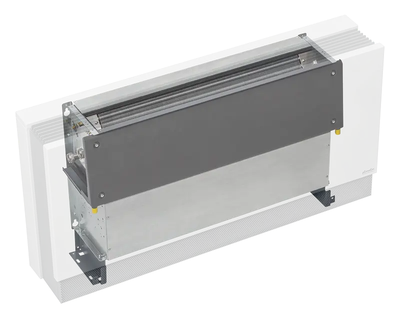
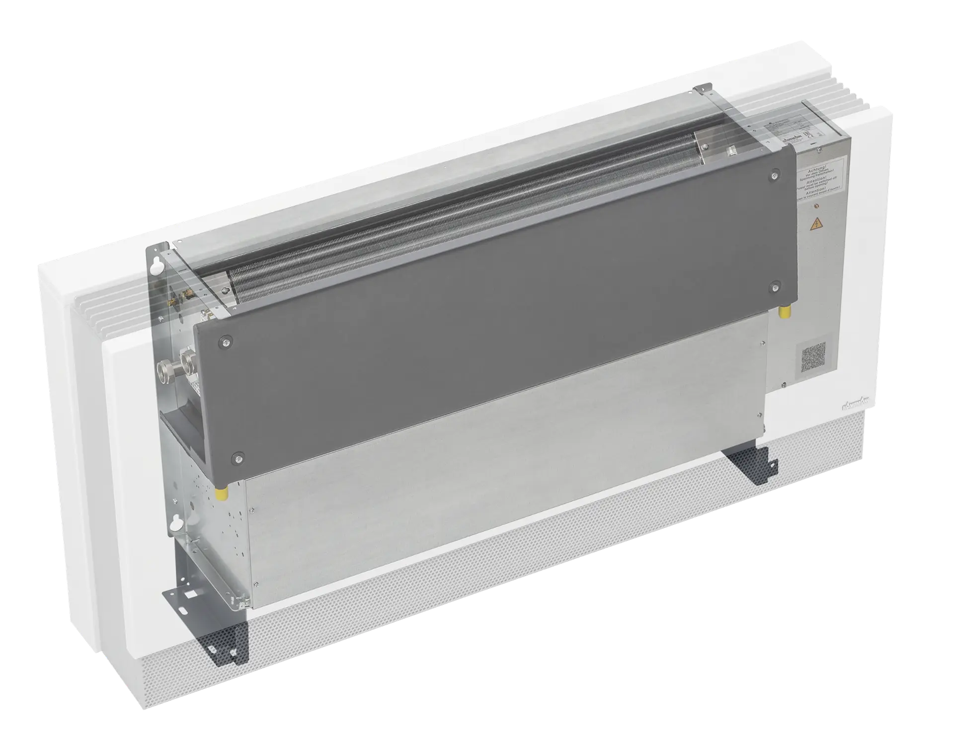
The installation location determines the basic structure of the unit.
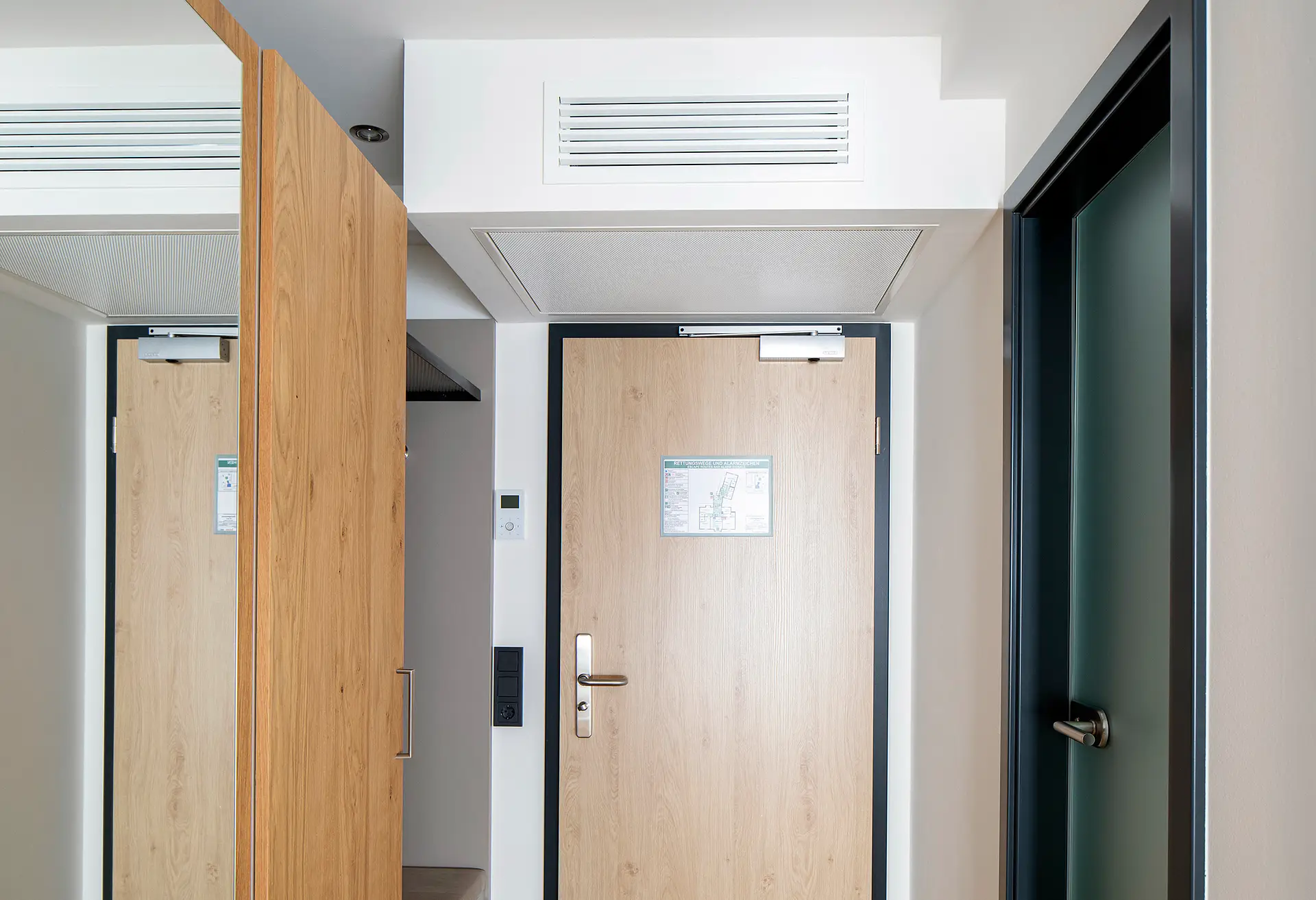
The ceiling version has been specially developed for horizontal installation on the ceiling, with the air outlet facing forwards. The wall-mounted model, on the other hand, is designed for vertical installation on walls, with the air outlet facing upwards.
The two variants are not compatible with each other due to the design differences - particularly in the condensate tray and condensate drainage. Each version is specifically designed for fixing, condensate drainage and maintenance accessibility.
The selection of the right variant should therefore always be based on the structural conditions and maintenance requirements.
| Installation site |
|---|
| Ceiling-mounted |
| Wall-mounted |
2-pipe system
With this design, the entire heat exchanger surface is available for temperature control, depending on the medium currently present in the pipe system (cold or hot water). Switch-over between heating and cooling takes place centrally via the building management system. This variant is particularly suitable for applications with seasonal switch-over and reduced installation effort.
4-pipe system
This version is suitable for sophisticated air conditioning concepts in which each room zone or unit can be switched over individually between heating and cooling. By routing the heating and cooling medium separately, the system offers maximum flexibility and comfort - ideal for buildings with changing usage requirements.
| Type of system |
|---|
| 2-pipe |
| 4-pipe |
Depending on the structural conditions and installation requirements, two connection variants can be selected:
Left or right connection.
These variants enable optimum adaptation to the pipe routing on site and reduce both installation work and costs.
For wall-mounted units, the connection side is defined from the viewing angle of the mounted unit.
For ceiling-mounted units, please refer to the technical drawing or installation instructions for the definition.
| Water connections |
|---|
| left |
| right |
Different filter types are available depending on the application area and the air quality requirements.
The standard version with an ISO Coarse filter primarily serves to protect the device by retaining coarse particles such as dust and fibers.
For applications with increased demands on indoor air quality, more powerful filters in accordance with ISO ePM, MERV or HEPA can be integrated as an option. These improve the indoor air by removing fine particles and aerosols from the intake air.
The suitable filter should be selected taking into account the project-specific requirements and the planned maintenance intervals.
| Filter class |
|---|
| Filter ePM1>50% (F7) |
| Filter ePM10>50% (M5) |
| ISO Coarse filter |
We offer various solutions for the control and regulation of our units, which can be used depending on the application and requirements:
Electromechanical control
This variant is ideal for simple applications. All integrated actuators are factory-wired to terminals and can be connected to our electromechanical accessories such as thermostats or external controllers.
KaControl MC1
Our comprehensive comfort control offers extended control options for individual rooms or appliance groups. It can be operated either via a touch display or a web interface. Thanks to on-site 0-10 V control or common communication protocols such as Modbus RTU & TCP, BACnet and KNX, this solution is ideal for all BMS applications.
| Control option |
|---|
| electromechanical with fault signal contact |
| electromechanical without fault signal contact |
| KaControl MC1, control box mounted |
| KaControl MC1, external control box |
Avoid the following:
The following must be observed when operating the unit below the dew point:
Serves as proof for certification systems, e.g:
Results per page
Results per page
Page 1 of 0
Results per page
Results per page
Page 1 of 0