

A perfect combination for effectively dispersing accumulated heat and saving energy
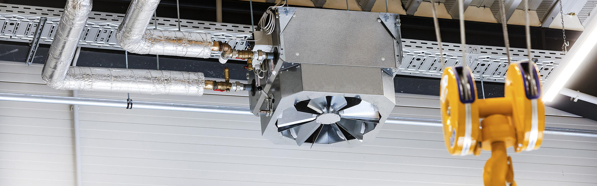
Unit heaters are THE indoor warm air solution for a wealth of applications. The units are fitted with continuously variable EC single-phase, sickle-blade rotor fans, which run smoothly, even at high power. Due to the EC technology used, they are only operated in the performance range that is required.
Unit heaters are very well suited for countering a phenomenon that occurs frequently in industrial sheds: accumulated heat under the ceiling. Kampmann uses its KaMAX diffuser (Kampmann Multi-Air-Mix), which reduces accumulated heat, especially in high halls and sheds, and thus prevents energy losses.
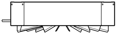
How is the KaMAX diffuser designed and how does it work?
The fins in the KaMAX are arranged in a circle. A control lever is used to adjust the fins to the required angle externally. Alternatively, the KaMAX diffuser can also be controlled remotely by a plug-in motor combined with a switch.
The swirl of the discharged air, that is its rotation, can be changed so that both horizontal and vertical air streams with variable induction properties and penetration depths can be generated. This prevents high temperature differences between the floor and ceiling. Heat that accumulates under the ceiling is drawn in and entrained in the air circulation. The precise setting of the KaMAX ensures that even large volumes of pleasantly heated air reach the occupied zone draught-free.
Which fin position is best for which hall height?
Below we describe three possible setting positions of the KaMAX fins at different ceiling heights and the respective effect on the diffuser.
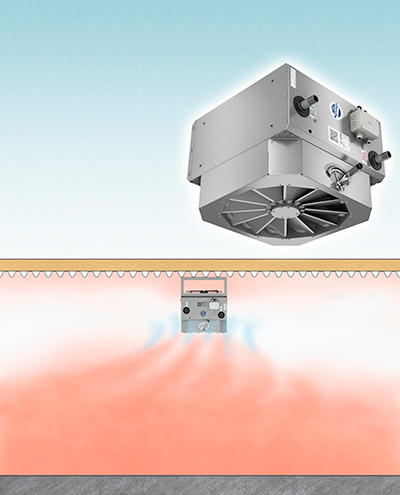
Hall height of 3 to 5 m | |
|---|---|
|
Horizontal position
|
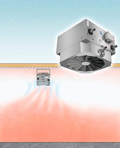
Hall height of 5 to 10 m | |
|---|---|
|
Slightly vertical position/centre position
|
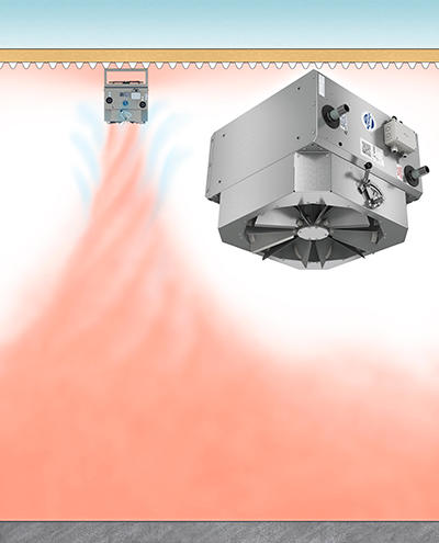
Hall height up to 20 m | |
|---|---|
|
Vertical position
|
KaMAX ensures the systematic mixing of indoor air, bridges thermal lift and thus prevents the formation of unwanted accumulated heat underneath the ceiling:
- Transmission heat losses are minimised
- Energy costs are reduced
- Comfort is enhanced in the occupied zone
Example of a design with a KaMAX diffuser
KaMAX in a vertical position
Our example shows a high-ceilinged industrial hall with a floor area of 3,200 m2 (40 m wide and 80 m long). Its height of 10 m produces a room volume of 32,000 m3 (3,200 m2 x 10 m).
The unit heaters are to be operated at low water temperature LPHW:
- Supply temperature 45 °C
- Return temperature 40 °C
- Room air temperature 20 °C
Based on a maximum installation height at medium speed, size 7 TOP unit heaters are selected with KaMAX diffusers in a vertical position.
At a control voltage of 8 V, the volumetric air flow of the size 7 unit heater is 5,910 m³/h.
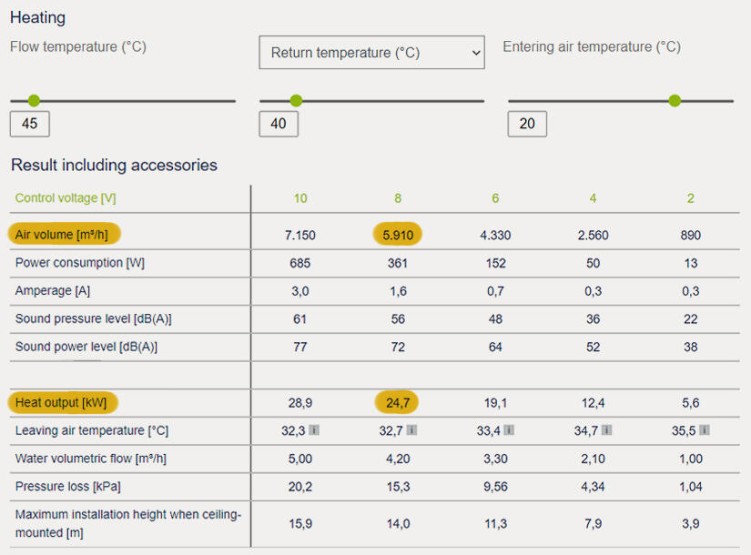
Result of the unit heater performance data calculation.
The KaMAX diffuser in a vertical position was selected as an accessory.
The following is calculated to achieve a minimum of 1.8 times the air circulation rate in the hall:
Room volume 32,000 m³ x 1.8 1/h = 57,600 m³/h total air volume flow to be moved.
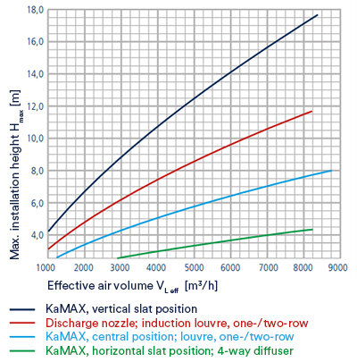
Comparison of the effective volumetric air flow of different diffusers with regard to the maximum mounting height (in this case, size 7 TOP unit heaters)
The number of units is calculated as follows: 57,600 m³/h / 5,910 m³/h = 9.7 rounded up to 10 units.
10 TOP unit heaters with KaMAX in a vertical position are therefore required to ensure sufficient air circulation throughout the entire hall. The entire air volume of the hall is entrained.
The heat output of the selected unit is 24.7 kW. This results in a total heat output of 247 kW (24.7 kW x 10 units) for the hall.
We provide our unit heater calculation program online, which also takes thermal influences into account for correct design. Calculate the heat outputs and other technical data with just a few clicks.
The benefits for you: At the end of the calculation, download the appropriate data sheet containing a lot of other information (shown here the result of our design example) or the specification wording. Use the wish list to save your individual product configuration including gross price, also including accessories if you wish. You have the option of managing entire projects by setting up a customer account.
The type of unit heater selected in our example can be operated in the design case at medium speed with 8 V control voltage. Thus, there are sufficient reserves even in special situations, e.g. at extremely low outside temperatures or if necessary for ultra-rapid heating-up in the morning.
As a rule of thumb, the higher the hall, the larger the size of unit heater.
The design and planning of unit heaters depends on more than just the heat load calculated. The maximum installation height needs to be considered with the ceiling installation of unit heaters! In addition, the necessary air circulation, structural and acoustic conditions, as well as unit-specific properties, such as the permissible sound level, also need to be considered.
Useful tip: We recommend designing with several smaller units, as the temperature is distributed more favourably here, the air speeds are slower, and lower noise can be expected.
Do you have questions about planning and design? No problem! Simply get in touch with us. We can support you in your project.